Industrial Gearbox Reliability: 7 Key Factors
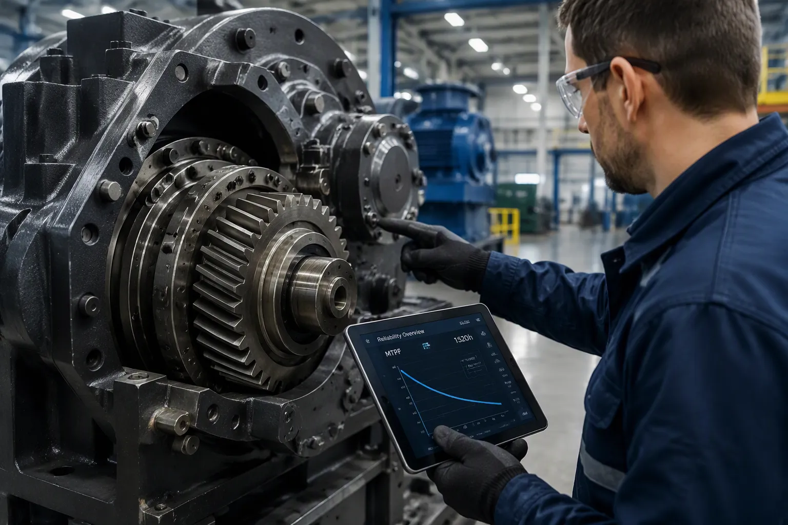
Industrial gearbox service life and reliability depend on seven controllable factors: lubrication, temperature, contamination, vibration, overloading, misalignment, and selection. Most premature gearbox failures trace back to one or more of these factors, not to the gearbox itself.
Failure cause | Share of premature gearbox failures |
|---|---|
Lubrication issues / deficiencies | 60% |
Alignment and installation errors | 20% |
Overload and shock events | 12% |
Contamination | 5% |
Manufacturing defects | 3% |
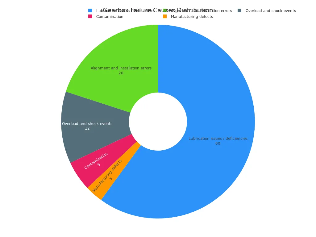
Each factor affects reliability in a distinct way. Practical steps prevent failure and extend industrial gearbox service life. The sections below explain both the impact and the countermeasures.
Key Takeaways
Lubrication problems cause most gearbox failures. Check oil levels and test oil regularly.
High temperatures break down oil and speed up wear. Keep gearboxes within safe temperature ranges.
Contamination damages gearboxes. Use good seals and filters to keep oil clean.
Vibration monitoring catches problems early. Fix issues before they cause breakdowns.
Overloading accelerates surface fatigue and breaks teeth. Size the unit correctly for peak loads.
Correct alignment prevents uneven wear and bearing stress. Install with precision.
Proper selection forms the foundation for longevity. Match the gearbox to the exact application.
Lubrication and Industrial Gearbox Service Life
Lubrication is the most common root cause of premature gearbox failure. Industry reliability studies attribute over 60% of failures to lubrication inefficiencies, and the American Bearing Manufacturers Association reports that nearly two-thirds of bearing failures stem from improper lubrication. The oil film separates gear teeth and bearing surfaces. When that film weakens, metal contacts metal, and wear begins.
Lubricant Properties That Matter
Four properties determine whether a lubricant protects the gearbox. Viscosity is the fluid's resistance to flow, and it provides the protective film between gears and bearings. Viscosity must suit the gear drive size and speed. Temperature range matters because oil thins as it heats, losing film strength and load-bearing capacity. EP gear oils perform from -5ºF to 250ºF (-15ºC to 121ºC), while synthetics stay stable across a wider range. Load-bearing capacity depends on extreme-pressure additives that form a protective film against scuffing under boundary lubrication at start-up and shock loads. Oxidation resistance controls how long the oil lasts. Oxidation forms sludge, varnish, and acids that raise friction and corrode metal surfaces.
Low oil level is equally damaging. Insufficient oil causes overheating and rapid wear of gears and bearings. Regular oil level checks are essential.
Preventing Lubrication Failures
Prevention starts with correct lubricant selection for the application, speed, and load. Scheduled oil analysis then tracks condition. Viscosity should stay within about ±5% of the target grade, water content should remain below the AGMA limit of 300 ppm, and acid number above 4.0 signals a highly corrosive oil. Change intervals should follow OEM guidance and analysis results.
Maintenance Condition | Baseline Change Interval |
|---|---|
Initial break-in | 300–500 hours |
Normal maintenance (mineral oil) | 2,000–5,000 hours |
Synthetic oil | 8,000–10,000+ hours |
Heavy-load / high-temperature service | 1,000–2,500 hours |
These baselines protect industrial gearbox service life, but analysis results override them. Consistent lubrication discipline remains the single largest lever for extending industrial gearbox service life.
Temperature and Heat Management
Every gearbox carries two loads at once: mechanical torque and thermal stress. Heat originates from transmission losses, bearing friction, seals, and lubricant movement. Duty cycle directly influences heat generation, lubrication effectiveness, bearing life, seal wear, and gear tooth fatigue. A gearbox running intermittently at high load may outlast one running continuously near its rated limit, because rest periods allow heat to dissipate.
How Heat Accelerates Wear
Excessive heat attacks the lubricant first. High temperatures thin the oil, so it can no longer form an adequate protective film. Friction rises, more heat follows, and wear accelerates. Heat also speeds oxidation, and the oil forms sludge that clogs systems and reduces efficiency. Performance additives degrade as well, stripping the lubricant of its protective qualities.
The consequences compound. Standard gear units operate safely between 40°C and 80°C, and every 10°C rise above the limit halves lubricating oil life. Sustained high temperatures shorten lubricant life and rapidly accelerate internal wear. Watch for darkened oil, a burnt odor, sludge, metal particles, or foaming. Fine metal debris often appears well before visible mechanical failure.
Keeping Temperatures Within Limits
Temperature monitoring gives the clearest early warning. Compare readings against the bands below and investigate any drift.
Temperature Range | Status | Implication |
|---|---|---|
140°F–180°F (60°C–82°C) | Normal operating range | Designed operating zone |
180°F–200°F (82°C–93°C) | Caution | Should be investigated |
Above 200°F (93°C) | Dangerous | Rapid lubricant failure and internal damage |
*Note: These limits apply primarily to mineral oils. Synthetic lubricants can safely operate at higher temperatures (up to 120°C/250°F), provided seal materials are compatible.*
Cooling methods should match the thermal load and configuration. Air cooling uses fins or dedicated fans. Liquid cooling circulates coolant through the housing and is more effective, though the system is more complex. External heat exchangers pump hot oil through a radiator or water-cooled unit and return it, which suits high-power applications. Synthetic lubricants resist oxidation and retain thickness at high temperatures; confirm seal compatibility with the supplier. Keep cooling fins and fan covers clean, and keep ventilation unobstructed. Finally, manage load: continuous duty makes thermal limits more critical than peak torque, and even modest overloads accumulate heat over time.
Contamination Control
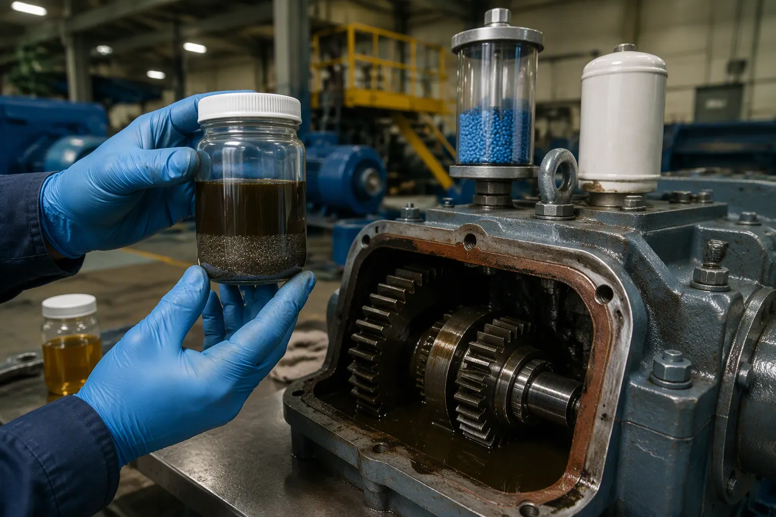
Common Contaminants and Effects
Contamination ranks among the most destructive factors in any gearbox. Contaminated oil appears dark, cloudy, or carries metal shavings. Those particles signal internal wear from contact fatigue. Water contamination creates a milky appearance. Dust, moisture, and chemicals cause abrasive wear, degrade lubricants, and produce corrosive wear on internal surfaces. Surface dirt speeds up part damage quickly.
Particle size matters more than most operators expect. Typical dynamic clearances measure only a few tenths of a micron to 5–10 microns, so silt-sized particles in the 1–10 micron range cause most gearbox damage. Water becomes equally dangerous once it exceeds the oil's saturation point, roughly 400–600 ppm for conventional gear oils. Free or emulsified water then destroys film strength, promotes rust and corrosion, and strips water-soluble additives. Practical limits should stay below 200–300 ppm. Common ingression sources include:
Airborne dirt and moisture
Wash-down and process water
Unfiltered new oil
Internally generated wear debris
Byproducts of oil degradation
Sealing, Filtration, and Inspection
Sealing and filtration form the first line of defense. Proper breathers and filters control airborne contamination. Seals need maintenance, and worn seals should be replaced at the first sign of wear. A bladder-type breather suits applications with minimal volume changes, because it seals the interior from the atmosphere while allowing air expansion and contraction. Breathers should include a filter and desiccant, and they belong in a clean, nonpressurized area. In harsh environments, a fully sealed gearbox with an expansion chamber and flexible diaphragm works best.
Method | Description / Effectiveness |
|---|---|
Lip seals | Affordable, require regular replacement; adequate for leaks and ingress |
Labyrinth seals | More expensive, more durable, better at excluding contaminants |
High-grade breather | Removes moisture and airborne debris before infiltration |
Filter cart | Cleans oil during filling and supports off-line filtration |
Sampling valves | Allow oil sampling during operation to detect contamination early |
Clean delivery matters as much as hardware. Fill and top-up through a filter cart or sealable canisters, and keep fill ports clean before use. Quick connectors at fill and sampling ports reduce ingested contamination. Permanent off-line filtration suits larger units with high oil volumes, and it can run while the gearbox is idle. New gearboxes commonly contain casting sand and machining swarf, so commissioning cleanliness deserves attention. A 3-µm filter during factory testing, followed by draining, flushing, and a new filter, removes this debris. Target ISO 4406 18/16/13 or better; this level can realistically extend gearbox life over three times.
Vibration and Condition Monitoring
What Vibration Reveals
Vibration analysis measures and interprets vibration signals to detect early signs of wear, misalignment, imbalance, lubrication issues, and gear tooth damage. Accelerometers mounted near bearings capture the signal, and Fast-Fourier Transform converts it into a frequency spectrum. Each fault leaves a distinct signature.
Fault condition | Characteristic vibration signature |
|---|---|
Gear wear and pitting | Rising gear-mesh frequency amplitude with sidebands at gear rotational speeds |
Bearing defects | High-frequency impacts at inner race, outer race, and rolling element frequencies |
Misalignment | Elevated axial vibration, typically at 2X and 3X rotational frequency harmonics |
Lubrication failure | Broadband high-frequency noise from metal-to-metal contact |
Frequency content points directly to the cause. Vibration at 1x running speed usually indicates imbalance. A fractured gear tooth produces clear impacts that oil analysis often cannot detect, because the fragment is too large to suspend in the oil.
Catching Problems Early
Condition monitoring works through the P-F interval. Point P is the moment a fault becomes detectable, such as a microscopic bearing race pit generating a high-frequency signature while the gearbox still runs normally. Point F is functional failure: a seized bearing, broken tooth, or sheared shaft. The window between them allows maintenance to be planned at the most convenient, cost-effective time.
"In a gearbox, oil analysis can tell you a gear is wearing, but vibration analysis can pinpoint which gear in a gearset where multiple gearsets are lubricated by a common reservoir."
— Industry Condition Monitoring Expert
Detection lead times vary by fault type. Bearing outer race defects typically show 45–90 days before failure, gear tooth cracks 30–60 days before fracture, and shaft misalignment 60–120 days in advance. Reported deployments predict 94% of gearbox failures at least four weeks before functional failure, with an average detection lead time of 11.5 weeks. Combining vibration with oil analysis extends warning from roughly four weeks to about eight weeks, since vibration alone misses lubrication-related failure modes.
Overloading and Load Management
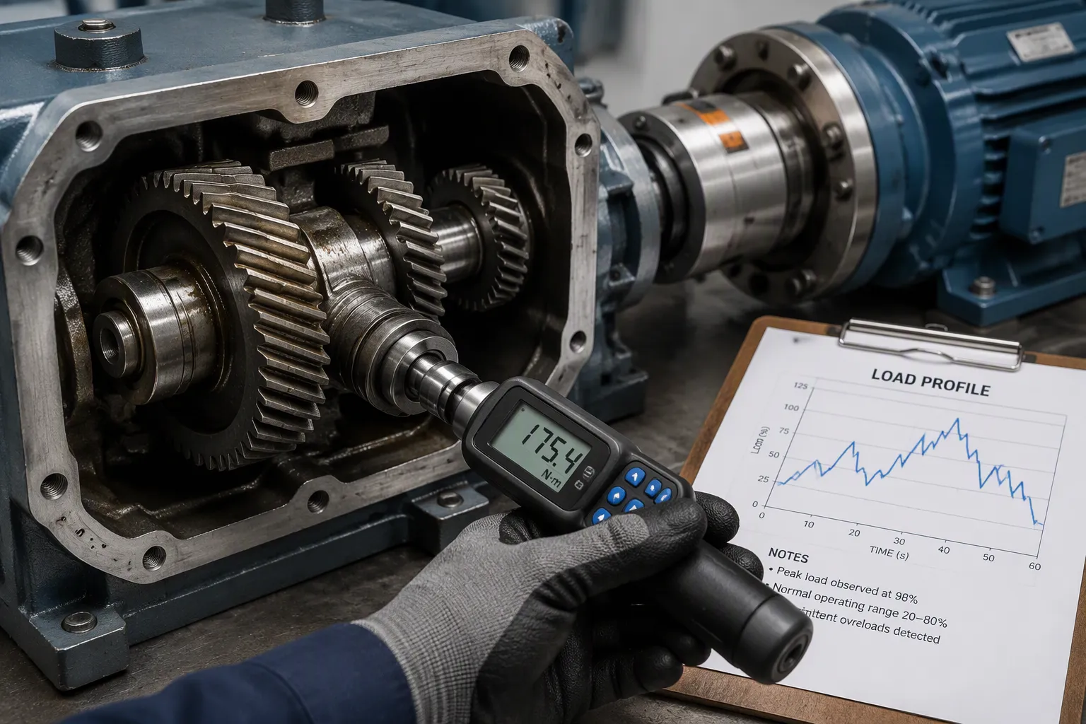
How Excessive Loads Shorten Life
Each gearbox is engineered for a defined torque range and service factor. Operating loads above that design capacity pass the excess stress to the gears, shafts, and bearings. Repeated overloads from jams, improper sizing, process changes, or frequent shock loads shorten gearbox life considerably. The damage follows predictable paths.
Failure Mode | How Excessive Load Contributes | Effect on Life |
|---|---|---|
Pitting and surface fatigue | High cyclic loading creates repeated stress | Subsurface cracks reach the surface as pits; progressive pitting weakens teeth and raises vibration and noise |
Broken gear teeth | Severe overload and shock loading | Cracked or broken teeth, loud impact noise, sudden vibration, loss of torque |
Overheating | Excessive load raises operating temperature | Accelerated lubricant degradation and component wear |
Bearing failure | Excessive loading adds stress to bearings | Rumbling noise, vibration, elevated temperature, shaft movement |
Gear tooth wear | Overloading combined with poor lubrication or misalignment | Accelerated abrasive and adhesive wear, scuffing, micropitting |
A gearbox may keep running after repeated overloads, yet wear, pitting, and cracked teeth accumulate beneath the surface. Tooth damage, shaft deformation, or bearing failure eventually follows.
Matching Load Profiles to Ratings
Sizing begins at the input shaft. Calculate input torque from the motor's full-load horsepower and operating RPM: input torque in lb-ft equals horsepower times 5,252 divided by RPM. Compare that result against the gearbox's rated input torque. A calculated value above the rating means the motor is oversized, regardless of output-side requirements. Peak events such as motor starting, sudden load changes, and emergency stops can produce torque spikes exceeding steady-state ratings by a factor of two or more, so margin at the input shaft is essential.
Document the complete operating requirement before selecting a unit: motor horsepower, rated and required output RPM, torque, shaft dimensions, rotation direction, mounting, load profile, operating hours, ambient conditions, and braking needs. Verify ratio, gear geometry, service factor, thermal rating, and overload capacity against the nameplate, drawings, manuals, and field measurements. Specify for the worst-case duty the unit will actually experience, not the upstream motor's nameplate horsepower. Apply service factors that reflect starts per hour, shock loading, and direction reversals. For high-inertia loads, calculate acceleration torque from load inertia and desired acceleration time, then confirm it stays within the momentary peak rating, typically 200–250% of nominal. Soft starters and variable frequency drives extend acceleration time and reduce peak torque. Finally, separate mechanical rating from thermal rating; on high-ratio worm reducers or in high ambient temperatures, the thermal rating may be the real constraint.
Misalignment and Installation Accuracy
A gearbox that fails every six months rarely suffers from bad luck. Chronic misalignment, lubricant contamination, or maintenance-induced errors usually explain the pattern. Misalignment ranks second only to lubrication as a cause of premature failure, and it damages several components at once.
Types and Consequences of Misalignment
Shaft centerlines can be angular, parallel, or both. Angular misalignment leaves the shafts at an angle to each other. Parallel misalignment keeps the centerlines parallel but offset. Combined misalignment presents both conditions together. Thermal expansion, soft foot, resonance, and sustained vibration or shock loads can also displace a unit from its correct position.
Misalignment Type | Description |
|---|---|
Angular | Shafts meet at an angle, creating an offset between them |
Parallel (offset) | Centerlines run parallel but are offset |
Combined | Angular and parallel conditions occur together |
Thermal expansion | Temperature changes displace shafts from alignment |
Soft foot | A mounting foot does not rest evenly on the base |
Resonance-induced | System natural frequency amplifies external vibration |
Vibration and shock loads | Prolonged vibration or impact gradually displace components |
The consequences spread through the whole drive. Uneven tooth contact concentrates stress and produces pitting, spalling, scoring, and increased backlash. Bearings carry unintended axial and radial loads, which leads to early spalling, overheating, and shorter life. Shaft movement wears seals unevenly, so lubricant leaks out and contaminants enter. Vibration and noise rise as components fight the improper alignment, and internal friction converts energy into heat. Misalignment also worsens over time as wear, loosening bearings, foundation settling, and thermal expansion accumulate.
Alignment Checks and Corrections
Precision alignment starts before any measurement. Confirm the foundation is rigid and clean, verify that motor and gearbox feet sit flat, and correct soft foot first. Check shaft runout and coupling condition, then set the coupling gap to the coupling manufacturer's axial spacing requirement.
Isolate and lock out the drive, then remove the guards.
Perform a rough alignment with a straightedge and feeler gauges.
Measure offset and angular error with dial indicators or a laser alignment tool.
Correct vertical error with precision shims and horizontal error by moving the adjustable machine.
Tighten bolts progressively to the specified torque, then recheck alignment completely.
Compare cold and operating readings where thermal growth matters, and refit guards before energizing.
Document every measurement for future reference. Periodic checks catch drift before it becomes damage.
Gearbox Selection for Long Service Life
Matching Specifications to Application
Correct selection begins with the application, not the catalog page. Torque and horsepower capacity must cover normal running loads, startup torque, shock loads, jam conditions, overhung loads, reversing duty, and emergency stops. Gear ratio and output speed must match the driven equipment. Mounting style, shaft configuration, environmental exposure, lubrication access, and thermal capacity all shape the final choice.
Application fit varies by industry. Mining and aggregates favor bevel helical, shaft-mounted, and planetary units. Food and beverage lines typically use helical, worm, or cycloidal gearboxes with washdown seals and food-grade lubricant. A heavy industrial mixer needs high startup torque capability, forced lubrication, and a high service factor. Matching these details to the duty protects industrial gearbox service life from the first day of operation.
Service Factor and Duty Cycle
The service factor determines achievable life. A service factor of 1.0 is typically suited for uniform loads and standard duty cycles (e.g., 8–10 hours/day). Applications with continuous 24/7 operation, heavy shock loads, or frequent starts require a higher service factor (1.5 to 2.0+) to ensure the gearbox is not operating at its absolute mechanical limit. Sizing solely on motor nameplate power ignores starting torque, shock loads, and abnormal conditions that dominate gearbox life.
Application Type | Load Condition | Typical Service Factor Range |
|---|---|---|
Light-duty conveyor | Smooth load, low shock | 1.0–1.25 |
Packaging machine | Moderate starts and stops | 1.25–1.5 |
Feeder or screw conveyor | Variable load | 1.5–1.75 |
Mixer or agitator | Heavy load, possible shock | 1.5–2.0 |
Heavy industrial machinery | Shock loading or long duty | 2.0+ |
A factor of 1.4 is adequate for most industrial applications. Undersizing strains gears and bearings beyond design limits, degrades lubricant, and raises noise and vibration. Oversizing adds drag, oil volume, and power consumption without a matching reliability gain.
When these factors are not carefully considered, the consequences can include overheating, mechanical wear, or even a complete gearbox breakdown.
Balance technical performance, application fit, regulatory compliance, and cost. A repeated failure in continuous duty calls for reviewing the application rather than repeating the same model.
Industrial gearbox service life and reliability depend on all seven factors working together. Lubrication, temperature, contamination, vibration, overloading, misalignment, and selection reinforce one another. Strong performance in one area cannot offset neglect in another.
Proper selection sets the foundation. Careful installation preserves it. Consistent maintenance sustains it through monitoring of lubrication, temperature, vibration, and alignment. These practices combined maximize reliability and reduce unplanned downtime.
Review your current practices against the seven factors. Identify the weakest link first, then correct it. Small, consistent improvements protect industrial gearbox service life over the long term.
Need Help Selecting the Right Gearbox?
Don't let premature failure cost you downtime. Contact CZ South Drive's engineering team today for custom sizing, application analysis, and high-reliability drive solutions.
Contact Our EngineersFAQ
Which factor causes the most premature gearbox failures?
Lubrication problems account for roughly 60% of premature failures. Incorrect viscosity, low oil level, and oxidized oil all break the protective film. Metal-to-metal contact then starts the wear cycle. Prioritize lubricant selection, oil level checks, and scheduled oil analysis before investigating other causes.
How often should oil analysis be performed?
Baseline intervals depend on the lubricant and duty. Mineral oil in normal service typically runs 2,000–5,000 hours between changes, and synthetics reach 8,000–10,000 hours or more. Sample at regular intervals within that window. Watch viscosity drift beyond ±5%, water above 300 ppm, and acid number above 4.0.
Is vibration monitoring worth the investment for a single gearbox?
Yes, when the unit is critical to production. Bearing outer race defects typically appear 45–90 days before failure, and gear tooth cracks 30–60 days before fracture. That window allows planned maintenance instead of emergency repair. Combine vibration with oil analysis to widen warning coverage.
What service factor should a new gearbox carry?
A factor of 1.4 suits most industrial applications. Light-duty conveyors with smooth loads may need only 1.0–1.25. Mixers, crushers, and machinery with shock loading call for 1.5–2.0 or higher. Size for the worst-case duty the unit will actually experience, not the motor nameplate rating.
Can a gearbox that fails repeatedly be saved?
Often yes, once the root cause is identified. Units failing every six months usually suffer chronic misalignment, lubricant contamination, or maintenance-induced errors. Precision alignment, corrected soft foot, and clean oil delivery address these patterns. Review the application before replacing the same model again.