Custom Aluminum Casting: Lightweight Design & Defect Control
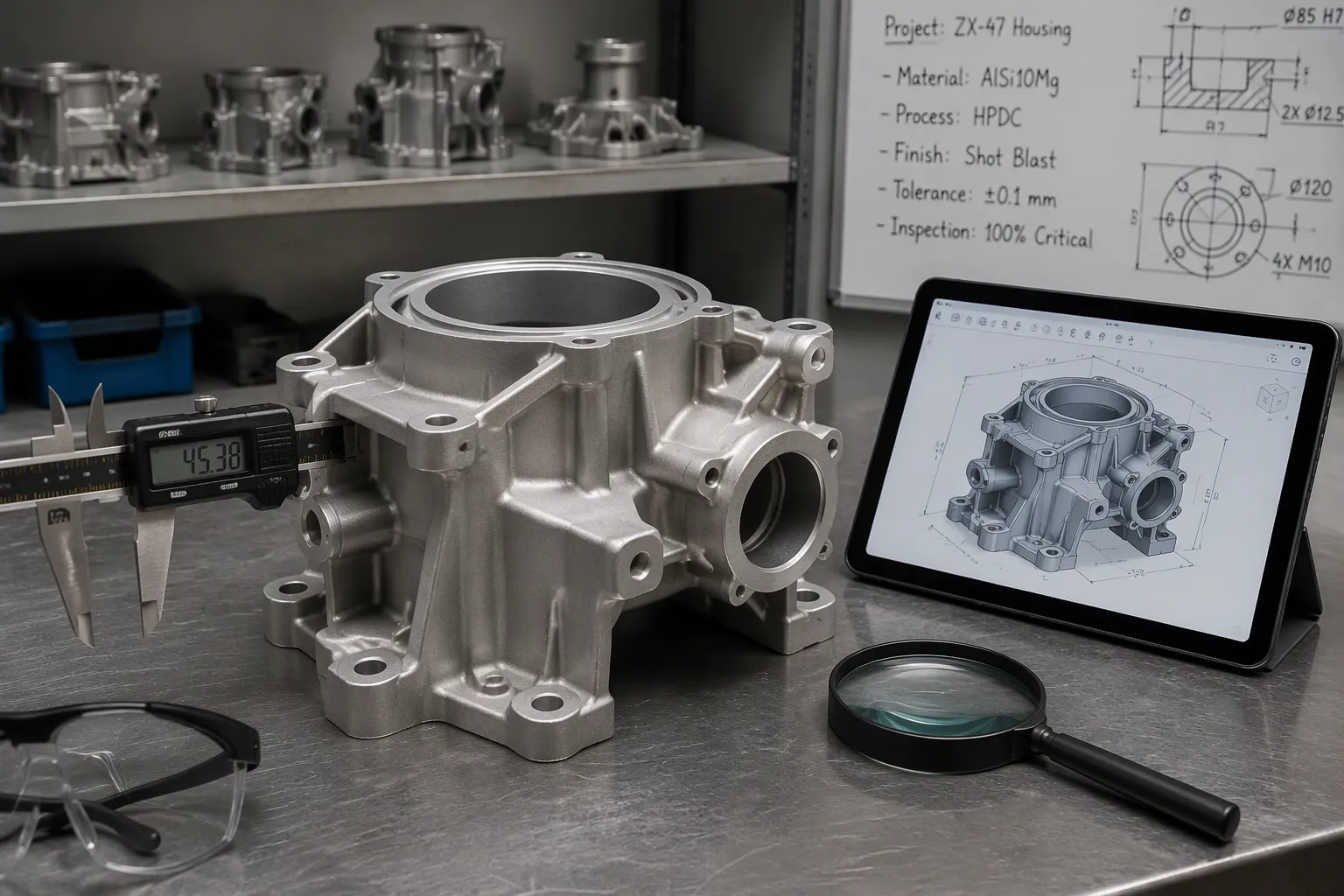
Reducing weight in custom aluminum castings for high-end equipment creates a direct conflict with structural integrity and performance. Engineers face a difficult question: how much material can be removed before the part fails? The answer lies in treating lightweight design strategies and defect control as one integrated system. Design optimization removes unnecessary mass. Process control prevents the porosity and shrinkage that thin walls invite. Inspection verifies that every part meets specification. This article follows that connected workflow from topology optimization through simulation, mold design, and final testing. Each stage reinforces the next. Success depends on this unified approach, not on isolated improvements.
Key Takeaways
Topology optimization removes unnecessary material while keeping the part strong.
Thin walls need careful control of temperature and cooling to avoid defects.
Casting simulation predicts problems before metal touches the mold.
T6 heat treatment and precision CNC machining complete the lightweight loop, locking in strength and dimensional accuracy.
A closed loop of design, process control, and inspection builds trust in lightweight parts.
Executing this integrated workflow demands real manufacturing infrastructure, not just software. Southdrive operates a 20,000㎡ self-owned factory supported by 30+ senior engineers and more than two decades of casting experience, bridging the gap between topology optimization and physical production. Backed by ISO9001, ISO14001, and ISO45001 certifications and exports to 60+ countries, its closed-loop system ensures that lightweight castings for global OEMs meet stringent international compliance and durability standards.
Lightweight Design Strategies for Custom Aluminum Casting
Weight reduction in custom aluminum castings begins with intelligent design decisions. Engineers must remove material where it serves no structural purpose. At the same time, they must preserve the load paths that carry operational forces. This balance defines effective lightweight design strategies for high-end equipment.
Topology Optimization Basics
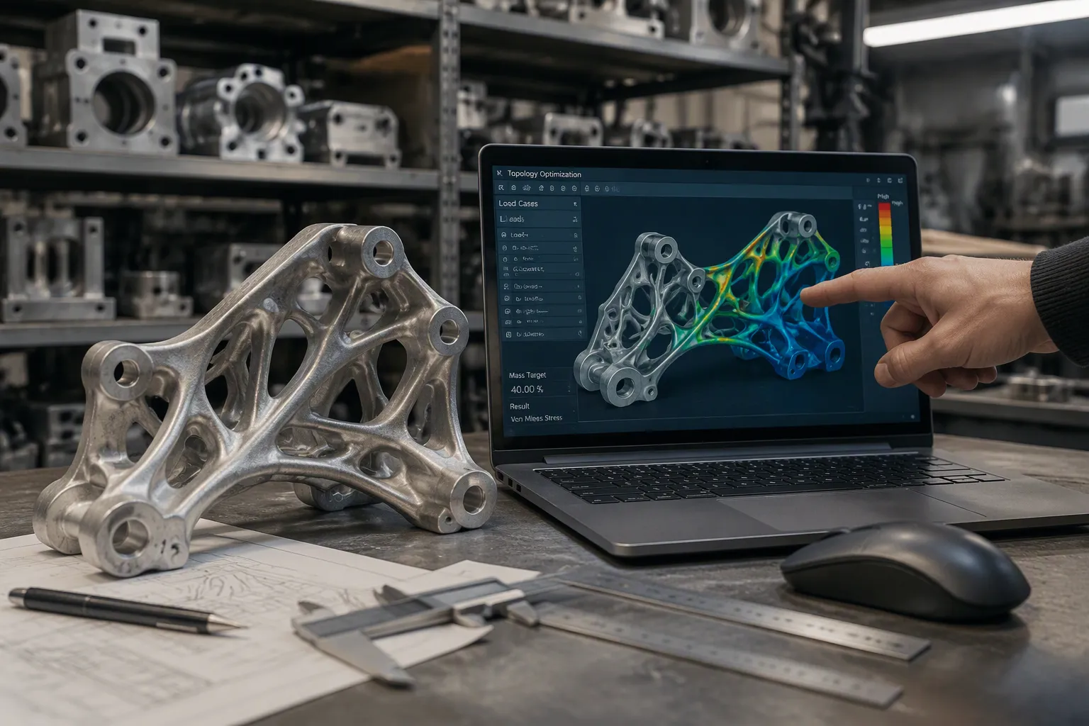
Topology optimization stands as a core method for achieving weight reduction without compromising strength. The process starts with a defined design space and a set of load conditions. Software algorithms then iteratively remove material from regions with low stress. What remains is an organic, efficient geometry that follows the actual load paths through the part.
This approach differs fundamentally from traditional design. Conventional methods add material to a baseline shape until it passes stress analysis. Topology optimization reverses that logic. It begins with maximum material and removes everything non-essential. The result is a component that weighs significantly less while maintaining stiffness and fatigue resistance.
For high-end equipment, topology optimization offers particular value. Fracturing pump gearboxes, mud pump components, and wind power housings all demand high strength-to-weight ratios. A lighter casting reduces inertial loads on bearings and shafts. It also lowers transportation costs and simplifies installation at remote sites.
Southdrive applies these principles across its casting operations. The company uses low-pressure and gravity casting processes to produce complex geometries that topology optimization generates. Low-pressure casting provides controlled filling and directional solidification. Gravity casting offers flexibility for larger, thicker-walled components. Both methods support the thin-walled, ribbed structures that optimized designs require.
Alloy Selection for Weight and Strength
Alloy choice directly affects both the weight and the castability of a component. Aluminum-silicon alloys dominate high-end casting applications. For gravity and low-pressure casting, A356 (AlSi7Mg) and AlSi10Mg represent two common options, each with distinct characteristics.
A356 offers an excellent strength-to-weight ratio after T6 heat treatment, making it ideal for structural components such as gearbox housings, pump bodies, and wind power hubs. AlSi10Mg provides high fluidity for thin-wall sections where complete mold filling is critical, and is increasingly specified for complex, ribbed geometries.
The selection process involves more than mechanical properties. Engineers must consider solidification behavior, shrinkage characteristics, and machining requirements. An alloy with superior strength may prove difficult to cast into a complex, thin-walled geometry. Conversely, an alloy with excellent flow characteristics may lack the fatigue resistance needed for cyclic loading.
Southdrive's engineering team evaluates these trade-offs for each application. The company's experience with low-pressure and gravity casting informs alloy selection from the earliest design stages. This integrated approach prevents late-stage changes that increase cost and delay production.
Heat treatment can further refine alloy properties (see the post-casting section below), allowing designers to specify thinner walls while meeting performance requirements. The combination of optimized geometry and properly treated alloy delivers maximum weight savings.
Wall Thickness and Structural Reinforcement
Wall thickness determines whether a lightweight casting succeeds or fails. Material removal reduces weight. Excessive removal creates defects that compromise the part.
Minimum Wall Thickness Guidelines
Aluminum alloys offer high fluidity and suit lightweight structural components. In high-pressure die casting, small sections can reach 0.040 in (1.0 mm), while large sections require at least 0.080 in (2.0 mm). These limits prevent cold shuts, poor fill, weak knit lines, and incomplete thin sections.
Practical guidance varies by alloy and process. In high-pressure die casting, A380 aluminum alloy works well at 1.5–2.0 mm minimum for many structural parts. Common aluminum alloys typically range from 1.5–3.0 mm, with 2.0–3.5 mm optimal for housings, brackets, covers, and complex geometries. High-fluidity AlSi12 reaches down to 1.0 mm in suitable designs. Magnesium alloys typically run 1.25–2.0 mm where strength-to-weight ratio is critical.
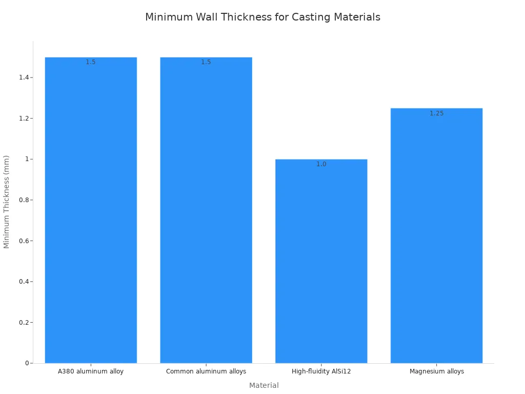
Gravity and low-pressure casting — the processes Southdrive specializes in — demand more conservative limits. For A356 (AlSi7Mg) in permanent-mold and low-pressure casting, a 2.5–3.0 mm minimum wall is typical, while a 3 mm (3/16") wall is the standard starting point for aluminum sand casting. Thin walls cause misruns and cold shuts because the metal cools too quickly. Most standard sand-cast parts use 4–6 mm to balance structural requirements with reliable castability.
Q: What is the minimum wall thickness to prevent structural failures in aluminum castings?
A: It depends on the process. For high-pressure die casting, aluminum alloys typically require 1.5 to 3.0 mm; recommended minimum wall thickness for A380 is 1.5–2.0 mm, and high-fluidity alloys like AlSi12 can reach 1.0 mm in suitable designs. For gravity and low-pressure casting of A356 (AlSi7Mg), plan on 2.5–4.0 mm, with 3 mm as the sand-casting starting point. Structural requirements, flow length, and inspection standards must always be verified.
Maximum wall thickness matters equally. Thick sections promote porosity and delayed cooling. Load-bearing or pressure-tight areas should stay under 5–6 mm. Beyond that threshold, designers should hollow the section and add ribs rather than add mass.
Ribbing and Reinforcement Techniques
Thin walls alone cannot carry bending and torsional loads. Ribs add stiffness without adding mass. A well-placed rib increases the moment of inertia far more than a simple thickness increase. Designers place ribs along principal stress directions. Rib height typically stays below three times the wall thickness. Rib spacing must allow the mold to fill completely.
Gussets reinforce corners where stress concentrates. Triangular gussets distribute load across a broader area. They prevent cracking at sharp transitions. Fillets at rib bases reduce stress risers and improve metal flow during filling.
Bosses accommodate fasteners and inserts. They require local thickening. Designers blend bosses into surrounding walls with gradual transitions. Abrupt changes create shrinkage porosity.
These reinforcement techniques support lightweight design strategies by preserving stiffness after material removal. Southdrive's low-pressure and gravity casting processes handle ribbed and gusseted geometries reliably. The controlled fill and directional solidification of low-pressure casting suit thin-walled, reinforced structures. Gravity casting accommodates larger components with thicker sections.
Simulation and Process Parameter Control
Casting Simulation for Defect Prediction
Casting simulation predicts porosity, shrinkage, and cold shuts before any metal enters the mold. Software models the filling sequence, thermal gradients, and solidification front. Engineers see where hot spots form and where the metal may freeze too early. These predictions guide design changes while they remain inexpensive to make.
Simulation supports lightweight design strategies by testing thin-wall geometries under real casting conditions. A wall that passes stress analysis may still fail during filling. Simulation catches that conflict early. It shows whether the gating system delivers metal fast enough to fill thin sections before solidification begins. It also reveals where shrinkage porosity will concentrate. Engineers then adjust rib placement, wall transitions, or alloy choice to eliminate the risk.
Temperature, Pressure, and Cooling Control
Temperature, pressure, and cooling rate determine whether a lightweight part fills completely and solidifies without internal defects. Metal temperature must stay high enough for thin sections to fill. Excessive temperature promotes gas absorption and coarse grain structure. Pressure control during low-pressure casting drives metal into the mold at a controlled rate. This prevents turbulence and gas entrapment. Cooling rate control manages the solidification sequence. Directional solidification feeds shrinkage from thick sections toward the gating system. Chills and cooling channels accelerate heat removal in heavy regions.
These parameters require continuous monitoring and adjustment. A small drift in temperature or pressure creates porosity that inspection will reject. Design reduces defect risk. Process control prevents defects from forming. Neither replaces the other. A well-optimized geometry still fails without disciplined parameter control on the shop floor.
Mold Design, Venting, and Gating
Mold design determines whether a lightweight casting fills completely and solidifies without internal defects. Thin walls leave little margin for error. Proper venting and gating systems work together to evacuate gases and deliver metal smoothly.
Venting to Prevent Gas Entrapment
Trapped gases create porosity, voids, and surface blemishes in aluminum castings. Adequate venting systems evacuate these gases quickly during mold filling. Good mold design ensures proper venting and feeding systems allow gases to escape easily while providing sufficient material to compensate for shrinkage.
Effective venting follows established guidelines. Combined vent and overflow volume should equal 10–15% of mold cavity volume to enable gas escape and reduce blowholes. Six to eight vent risers placed in the mold cavity ensure unimpeded gas evacuation during pouring. A green sand cope with dry cores improves gas permeability and reduces moisture-related defects. A flat cope design with cavities for core placement facilitates core integration and venting.
Permeable mold materials and coatings offer additional control. Porous ceramics, treated metals, or composite materials with controlled porosity allow gas escape while preventing liquid penetration. Strategically placed vents, porous inserts, or micro-channel networks optimized for mold geometry provide localized gas evacuation. Surface treatments such as chemical etching, laser processing, plasma treatment, or specialized coatings create controlled surface porosity. Porous mold inserts in areas prone to gas entrapment offer selective evacuation. Gas flow testing, pressure differential measurement, and permeability testing verify mold design effectiveness.
Gating System Design Principles
Gating systems enable both lightweight geometry and defect-free castings. Multiple gate configurations distribute metal flow evenly across thin sections, reducing turbulence and air entrapment. Bottom gating systems minimize oxidation and dross formation. Properly sized runners maintain adequate flow velocity without causing erosion. Overflow wells and strategically placed vents facilitate complete air evacuation.
Campbell's research identifies a critical gate velocity of about 0.5 m/s for aluminum. Above this threshold, the molten metal surface becomes unstable, folds over, and entrains oxide films. These bifilms act as crack initiation sites and reduce ductility. Gating design must keep gate velocities below 0.5 m/s by providing sufficient gate cross-sectional area while still achieving adequate fill time.
Expanding or unpressurized systems outperform pressurized systems for aluminum. Cross-sectional area increases toward the cavity, so velocity progressively decreases. This maintains laminar flow and allows remaining turbulence to dissipate before metal enters the cavity. Design rule: use an unpressurized expanding system with area ratios typically 1:2:2 to 1:4:4 (sprue:runner:gates). Ceramic foam filters at 20–30 PPI remove oxides and condition flow. These principles support lightweight design strategies by ensuring thin sections fill completely without defect-forming turbulence.
Post-Casting Precision Machining and Heat Treatment
Lightweight aluminum castings for high-end gearboxes, medical devices, and energy equipment rarely function as-cast. Secondary operations determine final mechanical properties and dimensional accuracy, and they must be considered during the lightweight design phase itself.
T6 Heat Treatment for Structural Integrity
To maximize strength-to-weight ratio, structural alloys such as A356 (AlSi7Mg) undergo T6 heat treatment: solution heat treating, quenching, and artificial aging. This cycle precipitates strengthening phases such as magnesium silicide, dramatically raising yield strength and hardness. The result allows engineers to specify thinner walls without risking deformation or fatigue failure under service loads. Controlled quench rates also limit residual stress and distortion in thin-walled housings.
CNC Machining of Thin-Walled Structures
Machining lightweight, thin-walled aluminum parts introduces its own challenges: vibration, chatter, and clamping distortion. Advanced CNC machining centers with specialized soft-jaw or vacuum fixtures are required to finish bearing bores, sealing faces, and mating surfaces to tight tolerances — often within ±0.02 mm — without inducing residual stresses that could warp the lightweight housing. Sequencing machining operations after heat treatment stabilizes dimensions and protects the integrity of the optimized geometry.
Inspection and Quality Assurance
Lightweight castings demand rigorous inspection. Thin walls and complex geometries hide defects that visual checks cannot find. Non-destructive testing methods reveal internal flaws before parts enter service. Without thorough inspection, weight reduction becomes a gamble with structural integrity.
X-Ray and Non-Destructive Testing
X-ray inspection detects internal porosity in aluminum castings. Areas with voids allow more radiation through the material. They appear as dark indications on the radiograph. Dense inclusions and thick sections absorb more radiation. Voids and cracks transmit more, creating contrast differences that highlight anomalies.
Radiographic Testing (RT) uses X-rays or gamma rays to produce images of component interiors. Dense inclusions and thick sections absorb more radiation; voids and cracks transmit more, creating contrast differences. RT is uniquely capable of detecting volumetric defects (porosity, inclusions) in welds and castings. Standards: ASTM E94, ASME Section V Article 2.
Radiographic Testing excels at subsurface volumetric defects such as porosity and inclusions, while surface-breaking flaws are additionally verified with visual and dye-penetrant inspection. RT verifies internal flaws on complex structures and inspects finished components without damage.
NDT Method | Capability for Subsurface Porosity | Key Strengths / Notes |
|---|---|---|
X-ray inspection | Detects internal porosity in aluminum die castings | Industry-standard method; produces permanent digital records |
CT scanning | Provides detailed visualization of internal structures | Best for complex geometries and R&D applications |
Ultrasonic testing | Effective for subsurface defect detection | Cost-effective for large volumes; requires flat surfaces |
Pressure decay testing | Identifies through-porosity | Pressurizes sealed castings and monitors pressure loss |
Different industries impose different acceptance criteria. Aerospace components require 100% X-ray inspection. Automotive structural parts have strict porosity limits. Medical devices specify leak-proof integrity. Electronics housings require pressure-tight enclosures.
Automated Defect Detection and Traceability
Deep learning-based automatic defect detection transforms quality assurance. Algorithms trained on thousands of radiographs identify shrinkage and gas holes automatically. They catch defects human inspectors may miss. They maintain consistent criteria across every part.
Southdrive's testing practices set an industry benchmark. Each casting undergoes hydrostatic testing to verify zero leakage. Every part receives a unique serial number for full traceability from ingot to shipment. ISO9001, ISO14001, and ISO45001 certifications confirm the integrity of the quality management system.
These inspection methods close the loop with Lightweight Design Strategies. Design optimization removes material. Process control prevents defects. Inspection verifies that every lightweight casting meets specification. Without rigorous testing, weight reduction becomes a gamble. With it, engineers trust thin-walled designs in demanding applications.
Full traceability with serial numbers provides accountability throughout the product lifecycle. Engineers trace any defect back to the exact casting and production run. This feedback loop improves both design and process over time.
Integrating Lightweight Design and Defect Control
Closing the Design-to-Inspection Loop
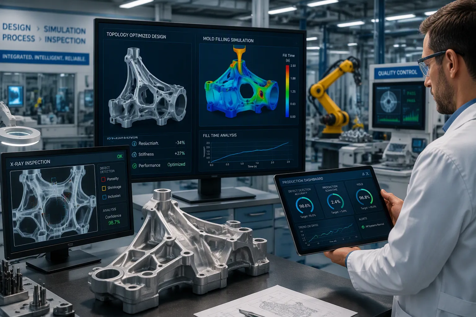
Design, simulation, process control, and inspection form one closed loop. Each stage feeds information to the next. Topology optimization defines the geometry. Simulation tests whether that geometry fills and solidifies properly. Process parameters control the actual casting. Inspection verifies the result and returns data to the design team.
This feedback loop separates successful lightweight programs from failed ones. A thin wall that passes stress analysis may still create shrinkage porosity. Simulation catches that risk before tooling begins. Process control prevents the defect during production. X-ray inspection confirms the part meets specification. When inspection finds a flaw, engineers trace it back to the exact casting and production run. They adjust the design or process and restart the cycle.
The loop never truly closes. Every production run generates data. Every defect investigation improves the next design. This continuous improvement mindset supports lightweight design strategies over the long term. Engineers gain confidence to remove more material because they trust the system that catches problems.
Artificial intelligence accelerates this loop. A wind power drivetrain study collected a large dataset of images across several months. A supervised learning model was trained with expert-labeled defects. Real-time monitoring ran in parallel with production. The feedback loop triggered immediate parameter adjustments upon defect detection.
Metric | Before AI Integration | After AI Integration | Improvement |
|---|---|---|---|
Defect Detection Accuracy | 85.0% (manual visual) | 99.2% (AI-assisted X-ray) | +14.2 percentage points; near-zero missed micro-porosity |
Production Downtime (hrs/month) | 12.0 | 3.5 | -70% reduction in line stoppages |
Production Yield (%) | 91.5 | 98.8 | +7.3 percentage points net yield gain |
Best Practices for High-End Equipment
High-end equipment applications demand disciplined practices across every production stage. Oil and gas, mining, wind power, and medical industries each impose unique requirements. The following practices apply across all of them.
Material control and melt practice — Maintain strict incoming material inspection, control scrap-to-new ratios, and implement routine refining and degassing protocols with controlled hold temperature and time for every heat.
Mold and gating optimization — Design gates, overflows, and vents for laminar filling and effective exhaust without vortex creation. Use flow and solidification simulation early in design to identify hot spots and feeding deficiencies.
Process parameter optimization — Set filling velocity curves and pressurization profiles (or high-speed switch points in die casting) to minimize turbulence and gas entrainment. Adjust holding pressure, specific pressure, and cooling sequence for compensatory feeding during solidification.
Tooling maintenance and coating control — Keep parting surfaces clean, repair wear on inserts and slides, control coating application to avoid trapped gas, and replace worn punches, sleeves, and pressure components promptly.
Inspection and corrective actions — Implement a testing matrix covering visual, dye-penetrant, ultrasonic, X-ray or CT, and pressure or leak tests. Use statistical process control to trigger corrective actions before defects escalate.
Design requirements — Balance wall thickness, minimize abrupt cross-section changes to reduce hot spots, and provide adequate gating, overflow, and venting in the tooling specification.
Quality assurance — Agree on acceptance criteria, sample plans, and corrective action workflow before production starts.
These practices reinforce each other. Material control reduces gas absorption. Gating optimization prevents turbulence. Process control manages solidification. Inspection catches what remains. For fracturing pump gearboxes, mud pump components, and wind power housings, this integrated approach delivers parts that meet both weight targets and performance requirements.
Lightweight design strategies and defect control reinforce each other. Removing material demands tighter process discipline. Simulation, parameter control, mold design, and inspection together determine final part quality. No single stage guarantees success alone.
High-end equipment applications in oil and gas, mining, wind power, and medical industries require this integrated approach. ISO certifications and full traceability with serial numbers provide the accountability these markets expect. Future advances in deep learning-based defect detection, simulation accuracy, and new aluminum alloys will push weight reduction further without compromising reliability.
FAQ
How thin can aluminum casting walls be without causing defects?
Minimum wall thickness depends on the alloy and the casting process. In high-pressure die casting, high-fluidity alloys like AlSi12 can reach 1.0 mm in suitable designs, and common aluminum alloys typically require 1.5–3.0 mm. Gravity casting and low-pressure casting demand more conservative limits: A356 (AlSi7Mg) typically holds a 2.5–3.0 mm minimum, with 3 mm as the standard starting point for sand casting. Thinner walls risk cold shuts and incomplete fill.
Which aluminum alloy works best for lightweight structural castings?
A356 (AlSi7Mg) and AlSi10Mg are common choices for high-end equipment produced by gravity and low-pressure casting. A356 offers an excellent strength-to-weight ratio after T6 heat treatment and is ideal for structural components. AlSi10Mg provides high fluidity for thin-wall sections. For high-pressure die casting, A380 remains a workhorse alloy. The best alloy depends on load requirements, geometry complexity, and casting process.
How does simulation prevent defects in thin-walled castings?
Simulation models filling sequences, thermal gradients, and solidification fronts before production begins. It predicts where porosity, shrinkage, and cold shuts will form. Engineers adjust rib placement, wall transitions, or gating design based on simulation results. This catches problems while changes remain inexpensive.
What inspection methods verify internal quality in lightweight castings?
X-ray inspection detects internal porosity and inclusions. CT scanning provides detailed visualization of internal defects. Ultrasonic testing identifies subsurface flaws. Southdrive performs hydrostatic testing for zero leakage and maintains 100% traceability with serial numbers. ISO9001, ISO14001, and ISO45001 certifications confirm the quality management system.
Can lightweight design and defect control work together effectively?
Yes. Design optimization removes unnecessary material. Process control prevents defects that thin walls invite. Inspection verifies every part meets specification. This integrated approach allows engineers to trust thin-walled designs in demanding applications across oil and gas, mining, wind power, and medical industries.
Turn Your Lightweight Designs into Reality
Don't let casting defects compromise your optimized designs. Send us your 3D CAD files, and Southdrive's senior engineering team will provide a free DFM (Design for Manufacturability) analysis and a competitive quote within 24 hours.
Get Free DFM Analysis & Quote →Please Contact Us!


Recent News
1.How Hard Skiving Reduces NVH in Klingelnberg Spiral Gears
2026-09-212.How to Select the Right Gearbox for Oilfield Applications
2026-09-143.1-Speed vs 2-Speed Marine Gearboxes: Which Offers Better Efficiency? (And the Gears Behind Them)
2026-08-134.Precision Gears Compared: Spur vs Helical vs Bevel vs Worm
2026-09-045.High Ratio Gearbox Types and Uses
2026-08-25